Hello
friends..
I’m posting
new PLC project ‘PLC Programming for Stepper Motor’. This project includes the
techniques used, programming and
interfacing. Advantages of PLC is that we can connect a Stepper motor Without
any Driver Circuit (depends on Output rating of PLC).
Technique
Used: (For Understanding Purpose Only)
·
Lets
consider 4 line Stepper Motor(A,B,C,D and COM)
·
Also
consider 4 step Truth Table
Truth table is shown below:

Above Truth table is just for reference.
As per your requirement you can take your own table.
When considering PLC, no direct
element is present to generate above sequence. Therefore many line programs are
required. Here I will explain how to
write any type of stepper motor program by a simple method.
Here I am using timer function TON
(Timer ON Delay). TON takes Delay to Turn ON, but we have to mention that Delay
time.
Taking 4 TON Timer, these timer having different
delay
(TON1 : TON2 : TON3 : TON4 :::: 1 :
2 : 3 : 4 )
The delay waveform shown below


TON4 is used for to reset all 3 TON
timers. It will reset every time.
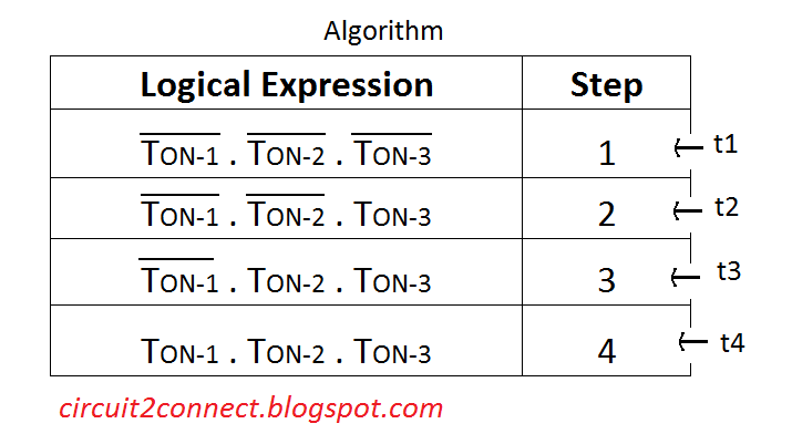
As per Above Waveform and Table we
get 4 time period that is t1, t2, t3, t4. We have to write a program so that in
every time period ‘t’ the program is made to run one STEP. So in 4 time periods
4 steps will occur. This will keep repeating.
Then for above condition we have to
write logical expressions as shown below
Programming:
As Per Above algorithm we write the
program here. Control inputs are ON and OFF. Output lines are named as A, B, C
and D. Physical Switch for ON is
NO Push button (Normally Open) and For OFF it is NC Push
button (Normally Closed).
We are using Timer TON (Timer ON
Delay) which takes a Delay time to turn ON.
We have to set that Delay time.
Because of continual switching of TON
step sequences are generated.
Ladder Diagram:

In above program I have set delay
for TON1, TON2, TON3 and TON4 as 1, 2, 3 and 4 seconds respectively.
For
simulation purpose we can use Siemen’s LOGO SOFT (Click To Download) and the ladder diagram
generated using this software is shown below

Block
Diagram:

Before
connecting Motor:
1) Check the Ratings for PLC output
Relay voltage and current.
2) If output Relay rating is less than
motor voltage Rating then you have to use External Relay, it should be Actuated
by a DC supply
Above
precaution should be taken before making the connection, otherwise wrong
ratings or connections will cause permanent damage to PLC.
All the
best…
Please
leave your queries in the comments section..
Thank you
Awesome things you've generally imparted to us. Simply continue written work this sort of posts.The time which was squandered in going for educational cost now it can be utilized for studies.Thanks s7-1500
ReplyDeleteThank you for your support..
Deletehi, how to do a bipolar stepper motor.
ReplyDeleteThank you, Also visit www.eduinformer.com. Thanks for this awesome article.
ReplyDeleteExcellent work.
ReplyDeleteI have a program for u
ReplyDeletecontact me abhishek.work15@gmail.com
Thanks
I cannot thank Mr Benjamin service enough and letting people know how grateful I am for all the assistance that you and your team staff have provided and I look forward to recommending friends and family should they need financial advice or assistance @ 1,9% Rate for Business Loan .Via Contact : . lfdsloans@outlook.com. WhatsApp...+ 19893943740. Keep up the great work.
ReplyDeleteThanks, Busarakham.